C-14 Modifications
| 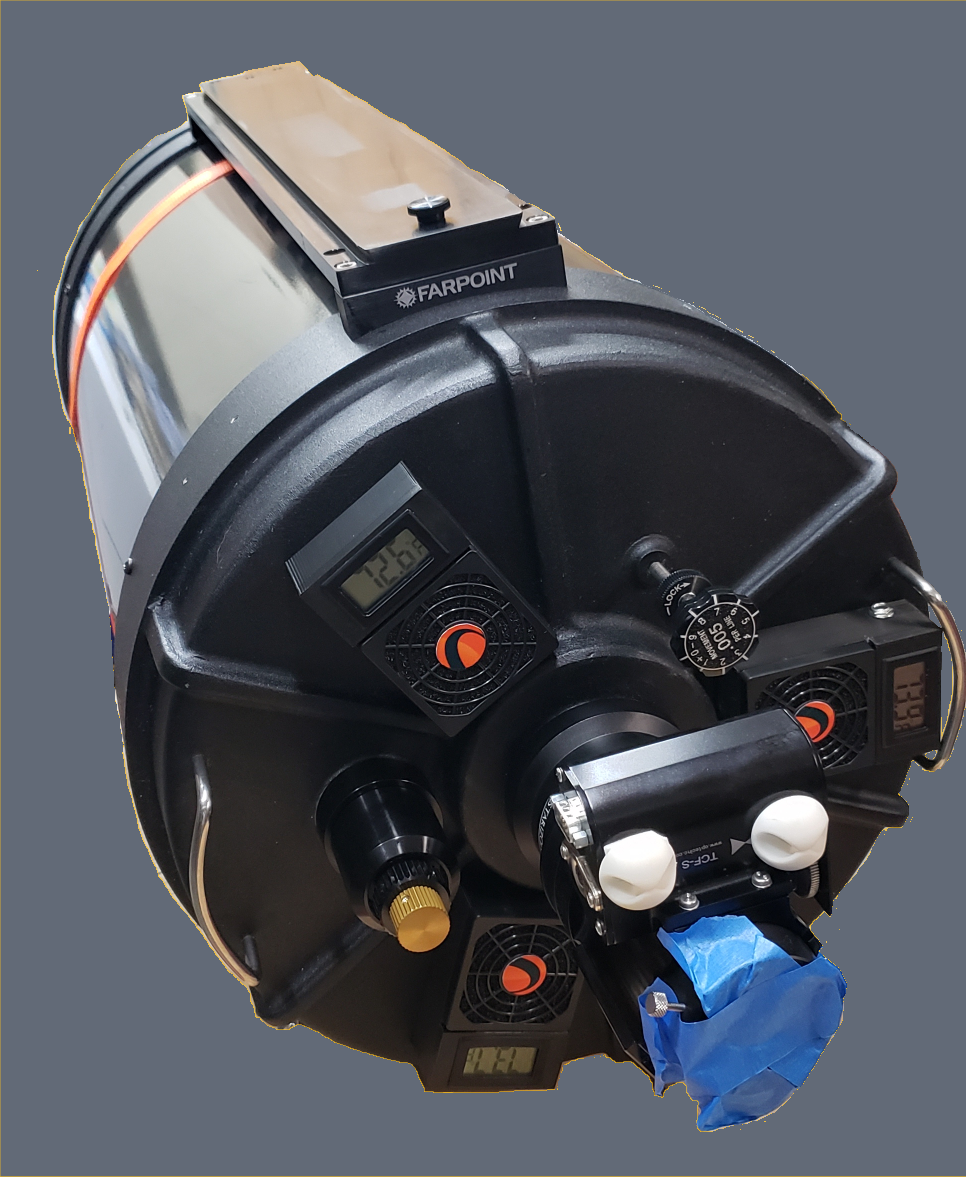 Click here to see all the pictures taken during this C-14 modification. |
| - RESOURCES RESEARCHED AND USED | |
| - TASK LIST | |
| - PROCEDURES AND ITEMS/TOOLS NEEDED FOR EACH TASK |
TASK LIST
| ||
| Hover the mouse over a photo to expand it for more detail. | ||
I. TAKE PICTURES!!!!!! | ||
| I tend to dive right into projects and I needed to remind myself to document what I do. Even with this Task I don't think I took enough photos. | ||
| Items/Tools Needed | ||
| a. DSLR | ||
| b. Cell Phone | ||
Procedures | ||
| a. Take pictures of everything | ||
| b. Take pictures of every step | ||
| c. Take pictures from various angles RETURN TO TASK LIST | ||
II. CHECK COLLIMATION PRIOR TO DIS-ASSEMBLY | ||
| Items/Tools Needed | ||
| a. Hotech Advanced CT Laser Collimator Set | ||
| b. Tripod | ||
Procedures | ||
| a. Check collimation and alignment per Hotech instructions | 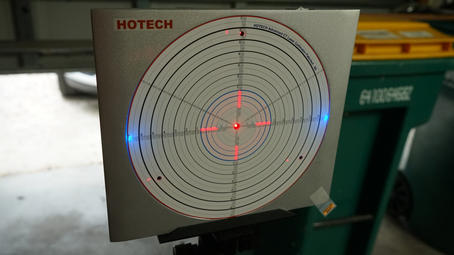 | |
| b. Hotech Advanced CT Laser Collimator Manual V8.pdf | 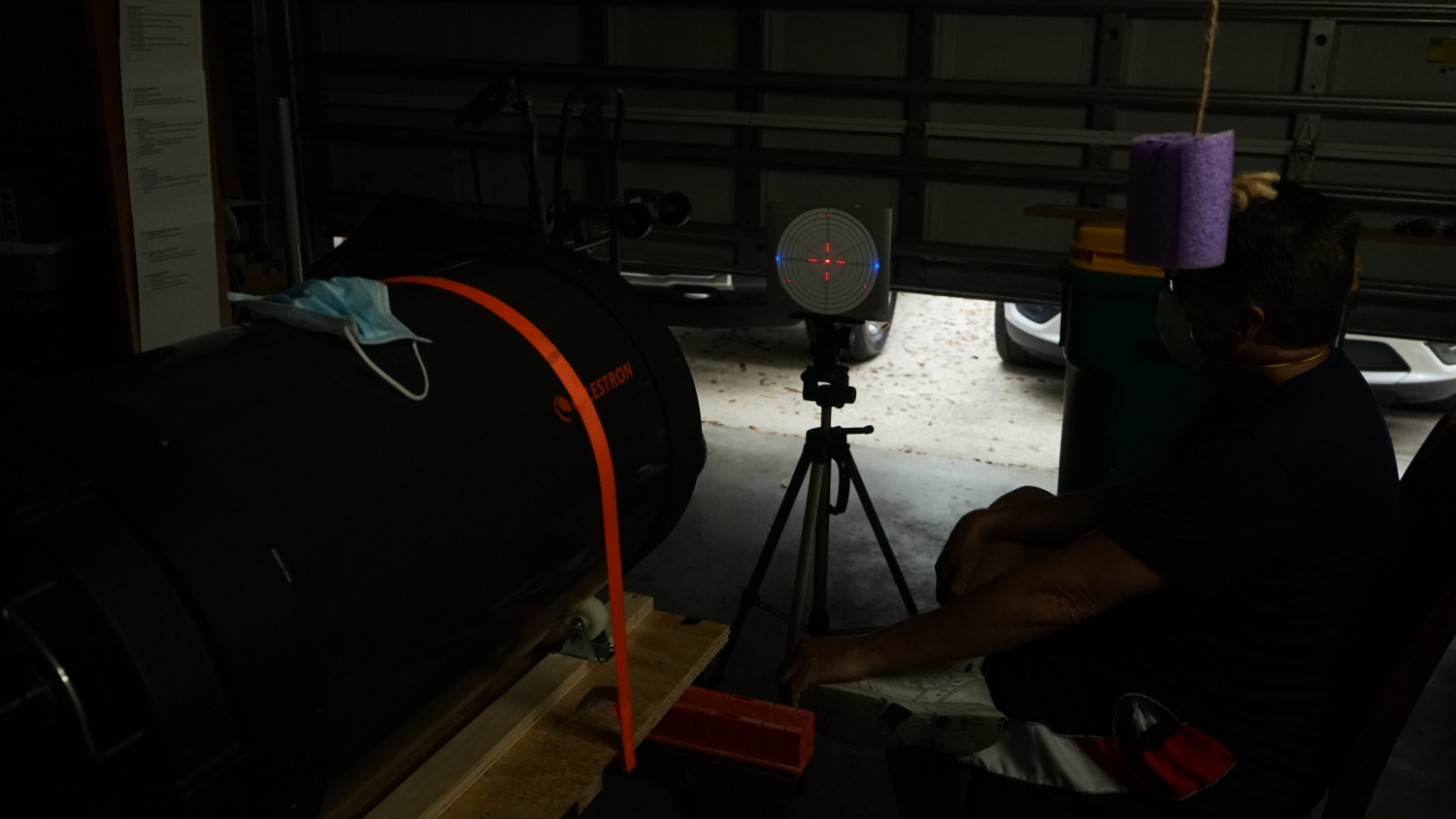 | |
| c. Video for Hotech ACT Laser Collimator |  | |
| d. Note all measurements RETURN TO TASK LIST | 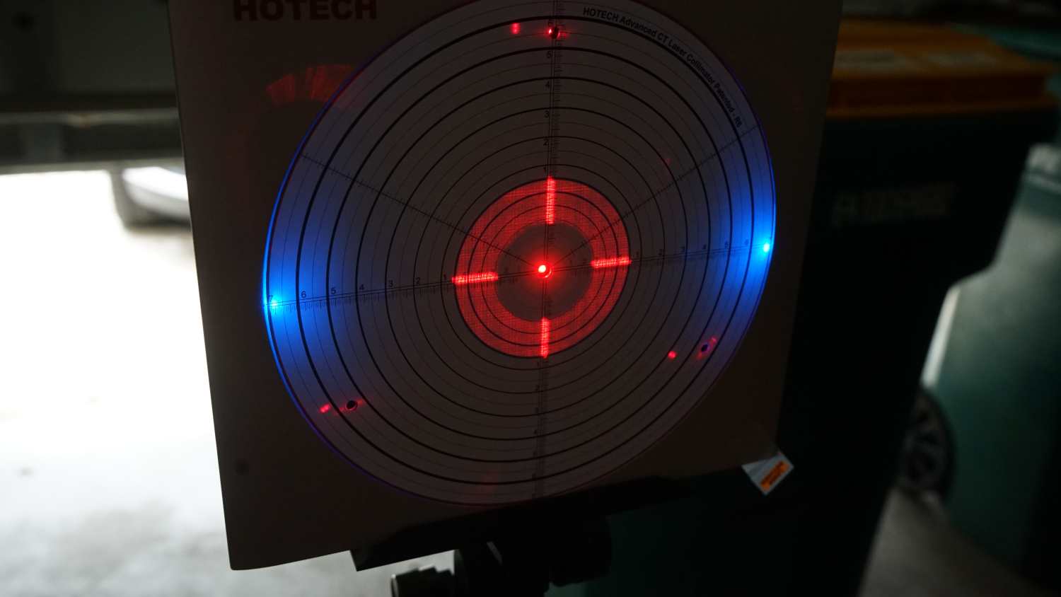 | |
III. DIS-ASSEMBLE OTA | ||
| Items/Tools Needed | ||
| a. Phillips screwdriver | ||
| b. 11/32" nut driver for interior nuts | ||
| c. Rubber mallet | ||
| e. Two (2) blocks of wood | ||
| f. Sheets, towels, or other coverings for Corrector and Primary | ||
| g. A ratcheting strap to prevent OTA roll | ||
| h. 2" non-swivel flat surface rubber wheels | ||
| i. 4ft x 18in x 3/4in plywood | ||
| j. Battery operated drill with phillips head driver | ||
| k. Two portable work "horses" | ||
| l. Screws to mount wheels to plywood | ||
| m. Clamps to secure plywood to "horses" | ||
Procedures | ||
| a. Build OTA holder/rotator of wood and rollers Screw the 2 blocks of wood to the plywood about 11" apart. Screw the wheels to the blocks of wood about 20" apart. Clamp the plywood to the saw horses in two places, one on each saw horse. | 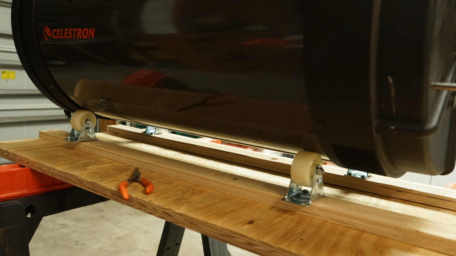 | |
| b. Place OTA on rollers horizontally and use a strap to prevent OTA roll | 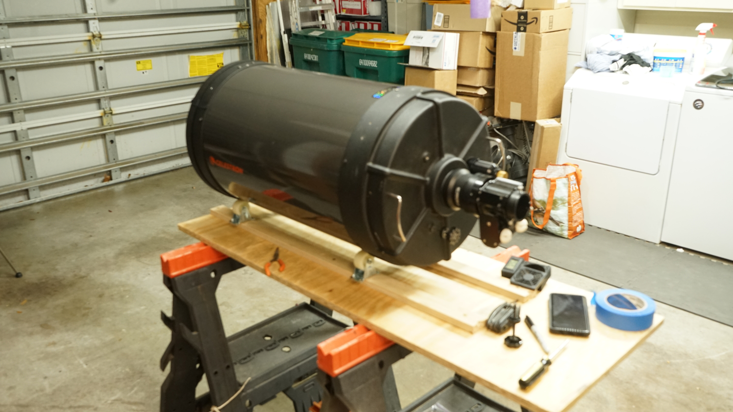 | |
| c. Remove orange dovetail Place bolts in a clear baggie and mark contents with a sharpie. Tape baggie to the orange dovetail. | 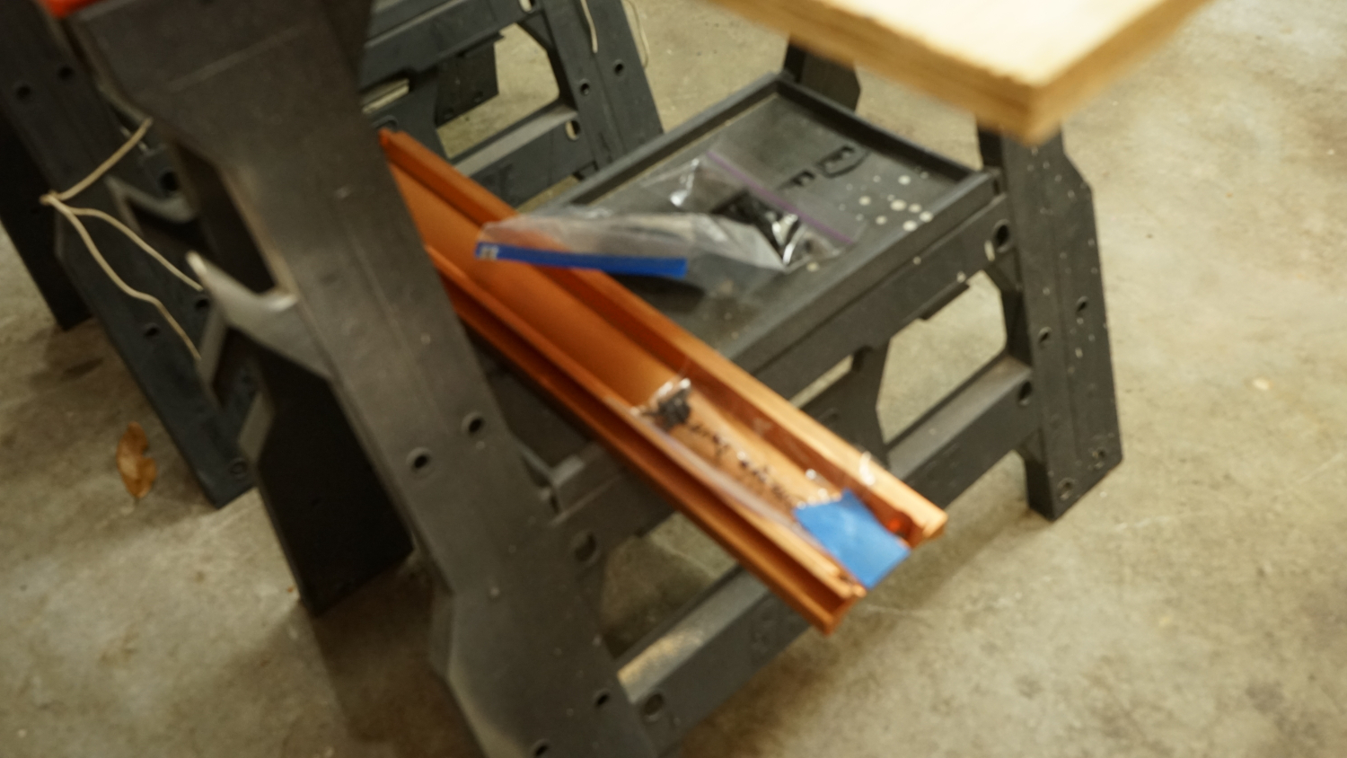 | |
| d. Mark the orientation of the OTA tube to the OTA rear cell | 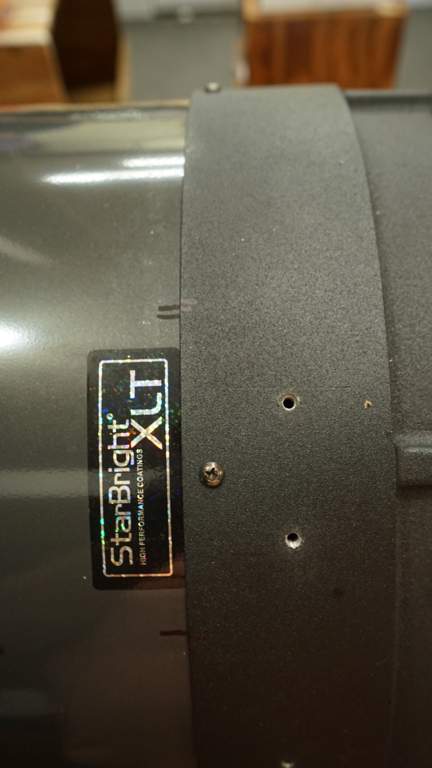 | |
| e. Mark the orientation of the OTA front ring to the OTA tube | 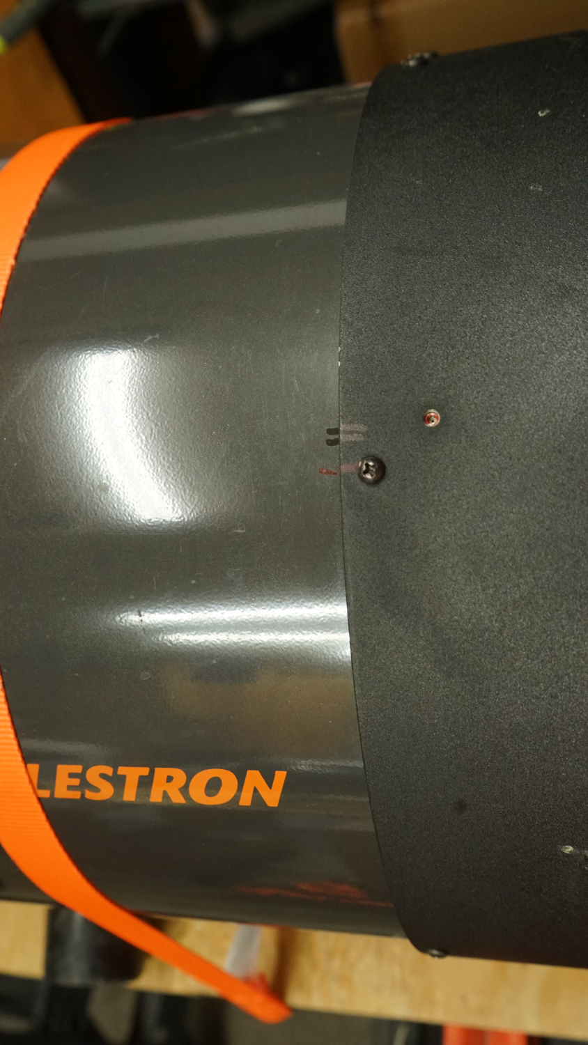 | |
| f. Remove Corrector | 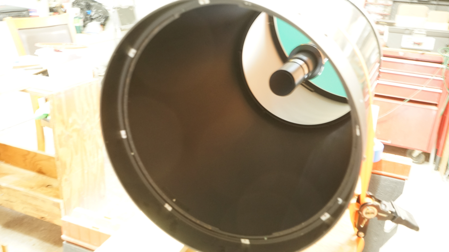 | |
| i. Wrap corrector | ||
| ii. Store inside in safe place | ||
| g. Remove front OTA ring | 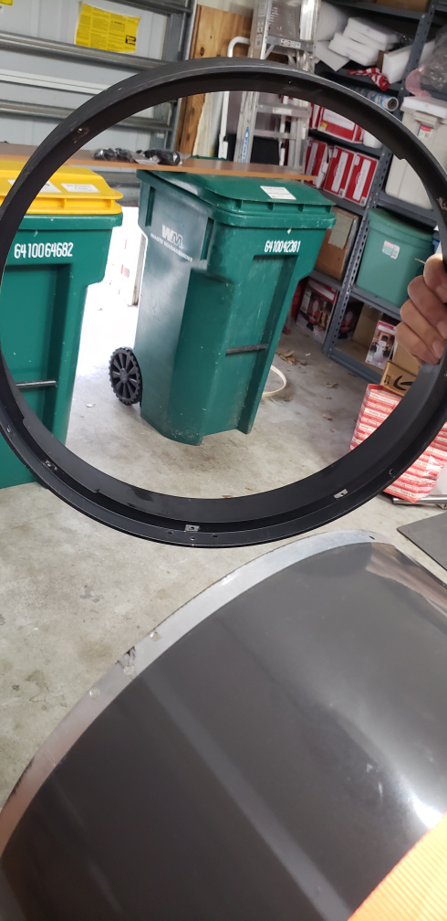 | |
| i. Remove (6) screws using phillips screwdriver and socket wrench | 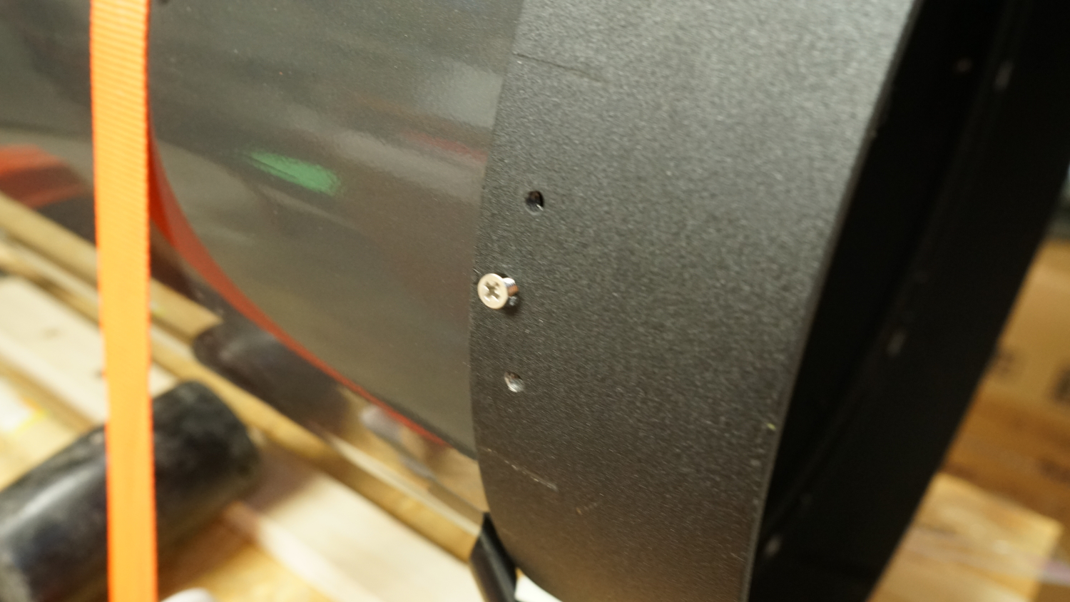 | |
| ii. Tap ring out (may have to use wood block and rubber hammer) | 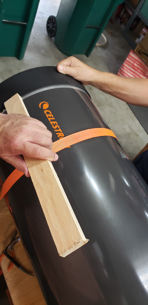 | |
| iii. Work way around ring sometimes not so gentle tapping | 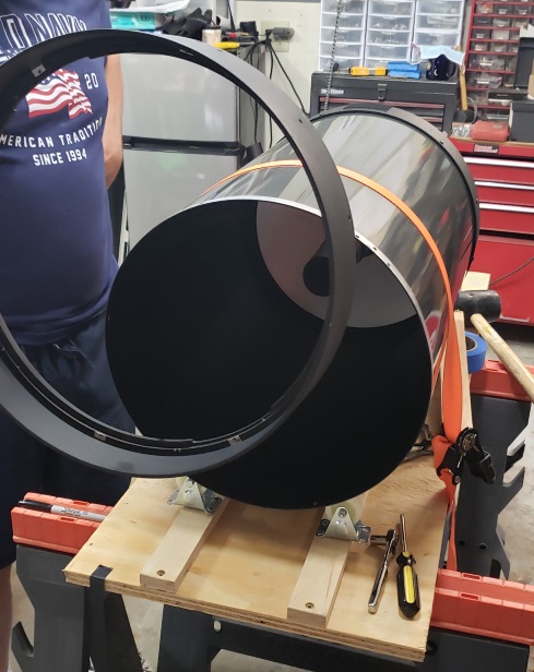 | |
| h. Remove baffle retaining C ring | 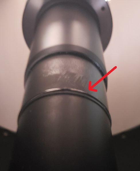 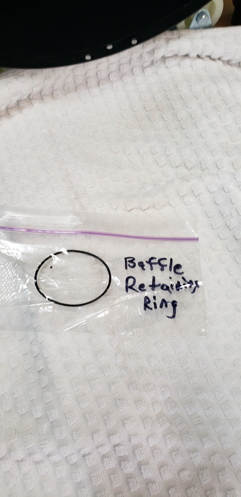 | |
| i. If ring is metal then separate tips and pull off | ||
| ii. If ring is rubber then roll it outward and off | ||
| i. Unbolt 3 focuser mounting bolts | ||
| i. Unthread the focuser internal mechanism from focus shaft | 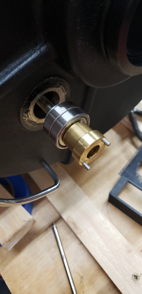 | |
| ii. The primary mirror is now free to be removed | 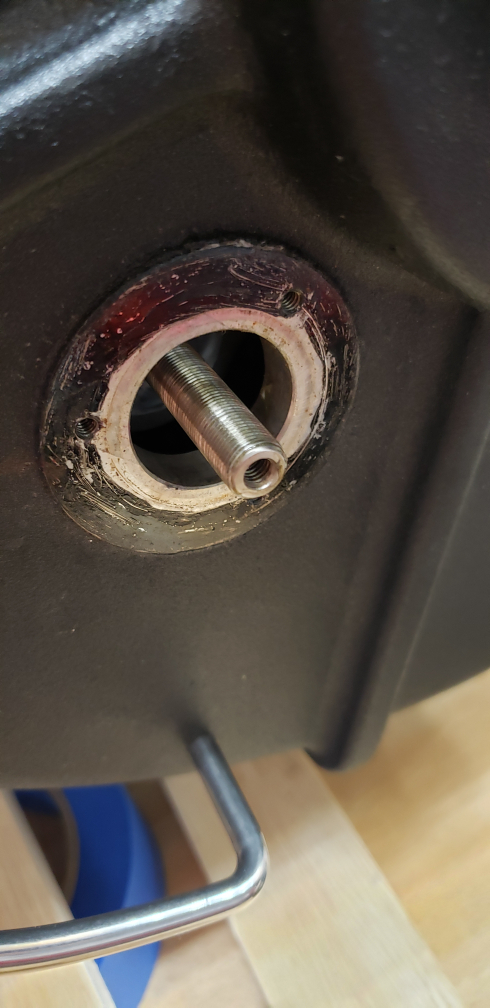 | |
| j. Remove primary mirror | ||
| i. Slide primary mirror forward using baffle | 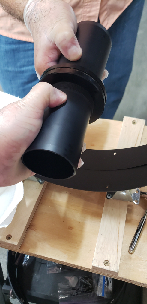 | |
| ii. Wrap mirror | 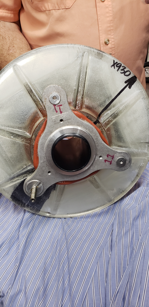 | |
| iii. Store inside in safe place | 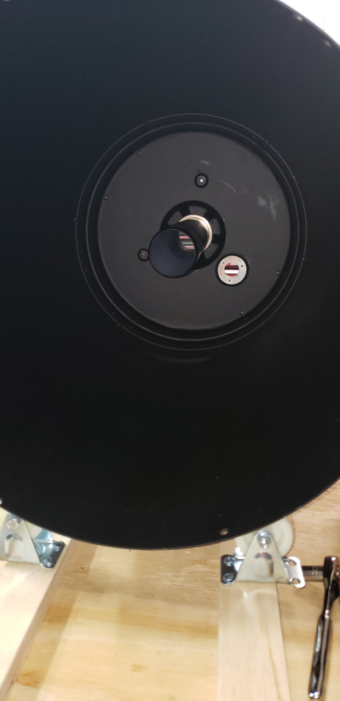 | |
| k. Remove the OTA tube from the OTA rear cell (optional) I decided not to remove the tube from the rear of the OTA. My choice was out of concern that the OTA would not seat properly when I attempted to put the tube back on. This was probably an unnecessary concern. It would also have made flocking the OTA easier. | ||
i. Remove screws using phillips screw driver | ||
| ii. Use wrench to hold interior bolts RETURN TO TASK LIST | ||
IV. INSTALL 1.25” VENTS, (4) AT FRONT-TOP AND (2) ON SIDE OF OTA FOR SB BAFFLE LOCKING COLLAR | ||
| In preparation of Step IX. Install Software Bisque C-14 Locking Collar I included the two holes for that installation. | ||
| (Note: Alternatively could size for 1" holes and vents such as Heyco 1" #2702) | ||
| Items/Tools Needed | ||
| a. File | ||
| b. 1/8” drill bit for pilot hole | ||
| c. 1.25” Step Drill Bit | ||
| d. (6) 1.25” Heyco vent plugs (1.25” – #2726) | ||
| e. Vent fabric | ||
| f. Vacuum | ||
| g. Hole punch | ||
| h. Hammer | ||
| i. Piece of wood the length of this inside diameter of OTA | ||
| j. Silver Sharpie | ||
| k. Blue painter's tape, 2" wide | ||
Procedures | ||
| a. Consider (4) vents, (2) at "top" 2-3” from upper dovetail (2) one each side 4" further from "top" holes | 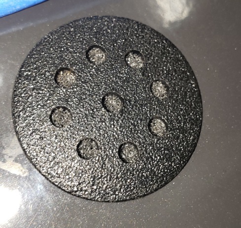 | |
| b. Measure 1” from front ring | ||
| c. Run a length of blue painter's tape 1" from the beginning of the gray tube paint at the front edge The length should be long enough to cover where each of the 4 new vent holes will be located. | 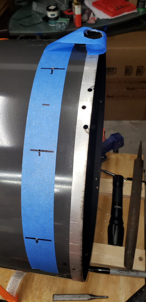 | |
| d. Measure and mark, ensure spacing is centered from OTA "top" and straddles Dovetail bar | 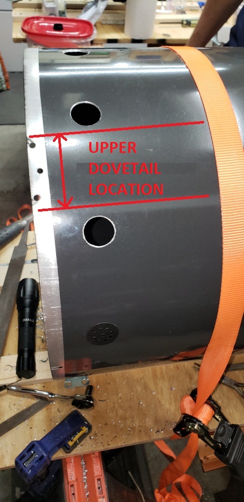 | |
| e. Measure (2) holes on left side from rear of OTA following Software Bisque's Baffle Locking Collar instructions I aligned these holes with the Celestron logo decal along the side of the OTA. | 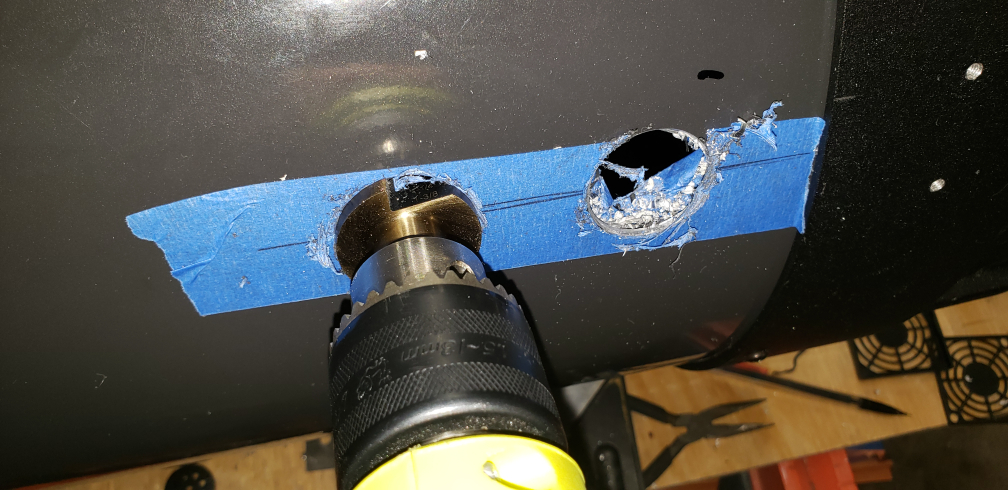 | |
| f. Lightly hammer tap the hole punch to make location so drill doesn’t drift | ||
| g. Drill 1/8” pilot holes | ||
| h. Drill using step or hole saw for desired vent diameter (1” or 1.25”) | ||
| i. File the holes (2) or (4) to ensure all burrs are removed | ||
| j. Cut to size and insert the vent fabric into round vents | ||
| k. Insert vent and ensure they snap in | ||
| l. Adjust hole size using file as necessary | ||
| m. Vacuum OTA and surrounding areas RETURN TO TASK LIST | ||
V. INSTALL (3) FANS, (2) PUSH AND (1) PULL AT REAR OF OTA ON OUTSIDE FOR FUTURE REPAIR | ||
| While I liked the more sleek look of fan covers only at the rear of the OTA, I also thought that if the fans were internal and I needed to maintain them or replace them it would mean dis-assembling the OTA again. I wanted to avoid this so I opted to place them outside the OTA. And being someone who values and appreciates the practical as well as the asthetic I decided to design and 3-D print specialized fan covers. These covers enclose the fans and hold thermometers I thought would be useful along with an on/off switch and power connector. | ||
| Items/Tools Needed | ||
| a. 60mm Mag Bearing fans (Sunon Maglev 60x60x25mm 12V Fan 2 Pin 1.5W MB60251V1-000U-A99) | ||
| b. 55mm Hole Saw Bit | ||
| c. 9/16” drill bit for 8-32 tap | ||
| d. 8-32 tap and rachet | ||
| e. File | ||
| f. Two 3D printed fan housings and one with rocker switch and power connector | ||
| g. Fan covers with Celestron Logo in center (printed on gloss paper and superglued) | ||
| h. (12) 1.5” 8-32 bolts | ||
| i. Vent Fabric | ||
| j. Soldering iron | ||
| k. Heat blower for shrink wrap | ||
| l. Shrink wrap tubing | ||
| m. Solder | ||
| n. Vacuum | ||
| o. Masking tape to remove drilled metal filings | ||
| p. Hole punch | ||
| q. Hammer | ||
| r. Power supply to test fans | ||
| s. Silver Sharpie | ||
| t. 1/4" drill bit | ||
| u. Blue painter's tape, 2" wide | ||
Procedures | ||
| a. Cover the baffle tube on the inside of the OTA completely and secure with tape This is to mitigate drill filings from getting onto the baffle tube. You'll want to wipe it completely before re-greasing it. | ||
| b. Place blue painter's tape over the focuser hole to prevent filings from entering. | ||
| c. Place blue painter's tape on back of OTA at each fan desired location | 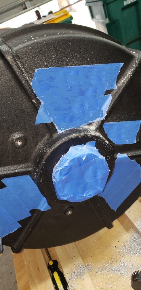 | |
| d. Measure, locate, and mark the location of fan center hole | 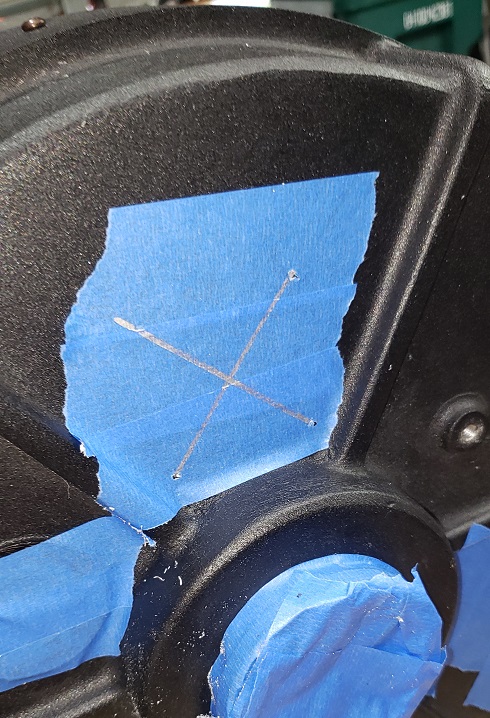 | |
| e. Use hole punch to mark center to prevent drift | ||
| f. Drill 1/8” pilot hole | ||
| g. Drill 55mm hole using hole saw | 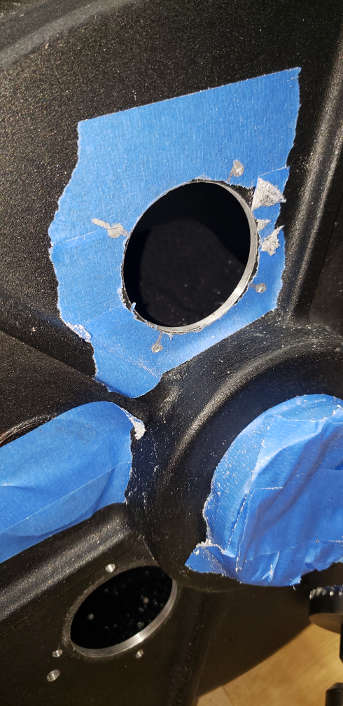 | |
| h. Use fan grill to mark fan bolt holes by centering the grill cover over 55mm bored hole | ||
| i. Use hole punch to mark to prevent drift | ||
| j. Drill 9/16” holes for four corners | 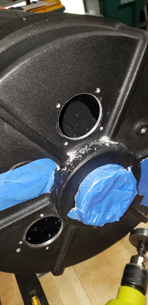 | |
| k. Tap all 4 holes using 8-32 tap | 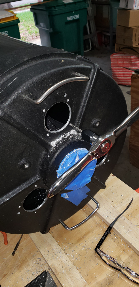 | |
| l. Repeat this for each of the 3 fans | 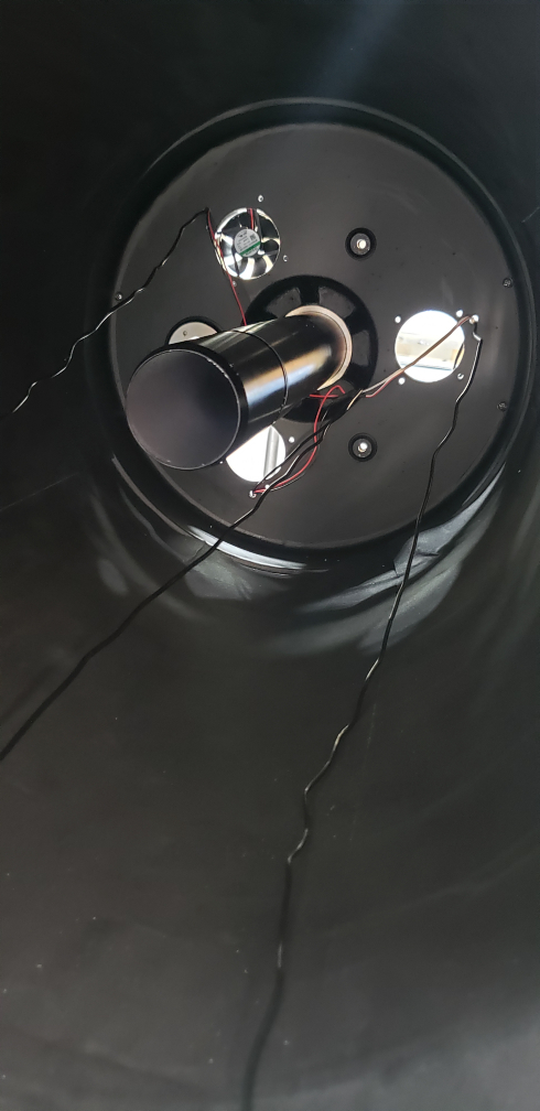 | |
| m. Use hole punch, 1/8", and 1/4" bits to drill holes for fan and thermometer wires Place hole about 1/2" above and to the left of the upper right fan bolt holes. | 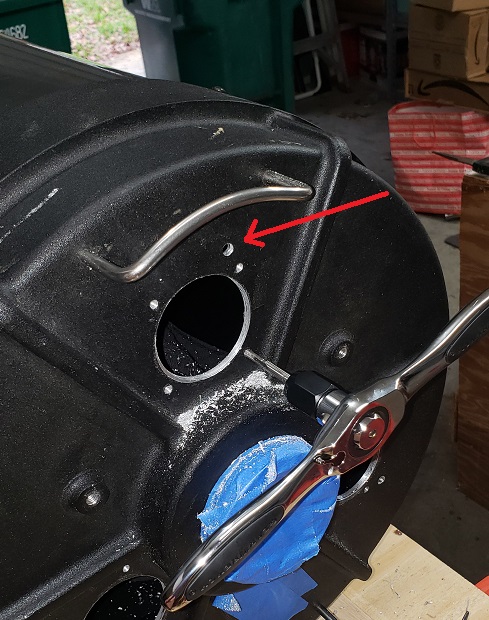 | |
| n. Orient the fan box cover with switch in convenient location | 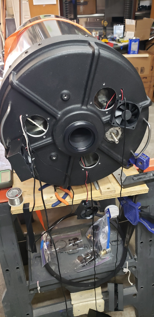 | |
| o. Feed wires through 1/4" fan and thermometer holes | 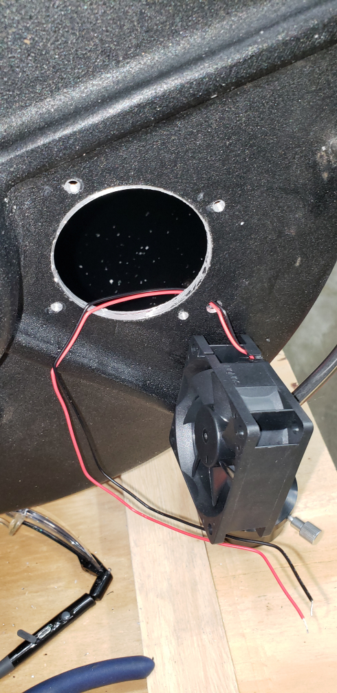 | |
| p. Place shrink wrap onto each wire | ||
| q. Solder each fan in parallel | 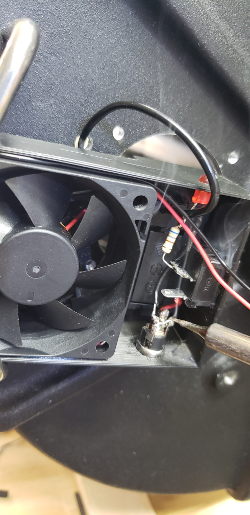 | |
| r. Slide heat shrink tube over each solder joint and heat with heat gun | 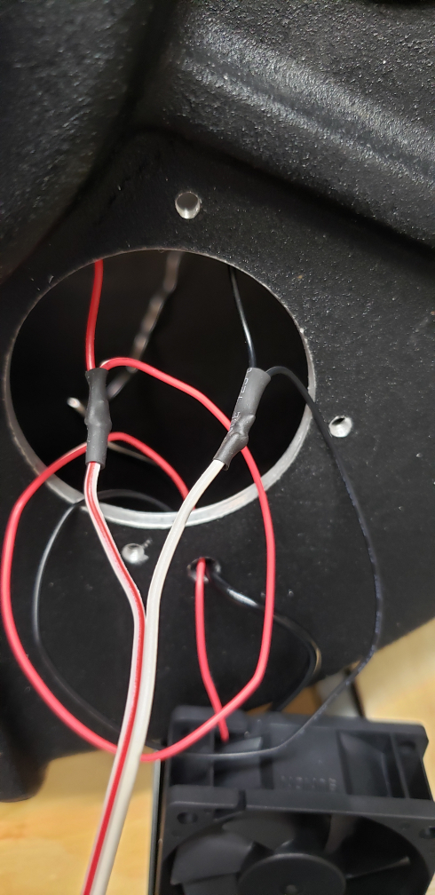 | |
| s. Vacuum the OTA inside RETURN TO TASK LIST | ||
VI. ADD FOUR SETS OF TWO THREADED HOLES ON SIDE OF OTA FOR FINDERS, ETC. | ||
| Items/Tools Needed | ||
| a. Drill | ||
| b. 1/8” drill bit for pilot hole | ||
| c. Hole punch | ||
| d. 9/16” drill bit for 8-32 tap | ||
| e. 8-32 tap and rachet | ||
| f. 8-32 x ½” screw or hex head bolts for new holes | ||
| g. Pencil | ||
Procedures | ||
| a. Note: 8-32 bolts are currently on side of OTA | ||
| b. Measure existing hole set separations and their location around OTA | ||
| c. Mark four sets of two hole new locations so they are uniformly spaced around OTA | 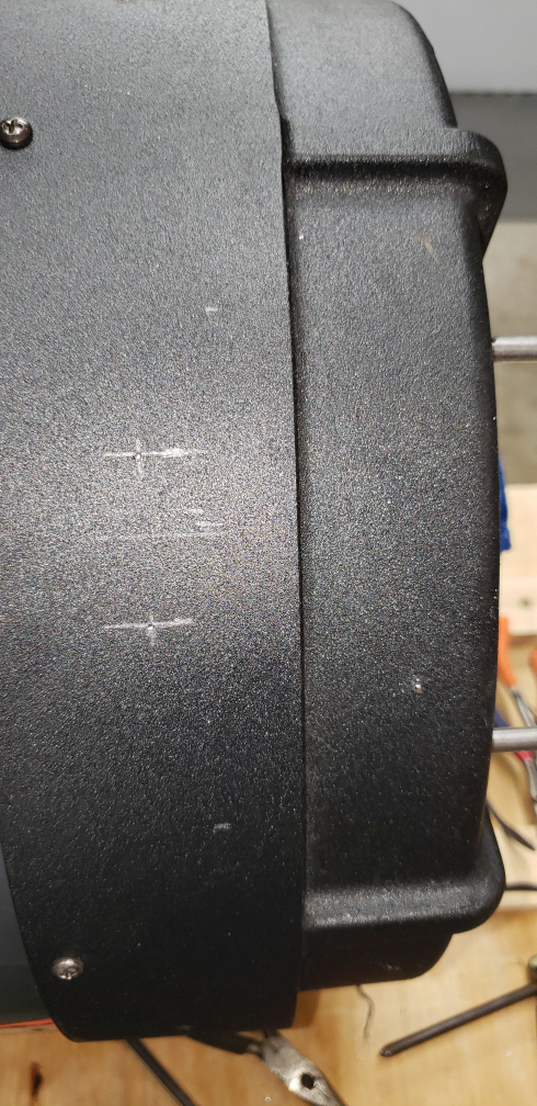 | |
| d. Use hole punch to prevent drill drift | ||
| e. Drill 1/8” pilot holes | ||
| f. Drill 9/16” holes for thread | 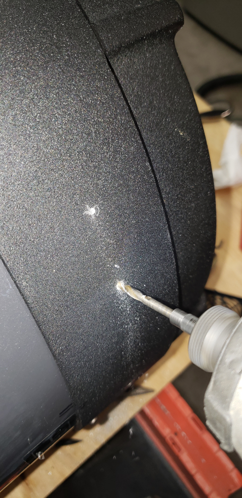 | |
| g. Tap 8-32 thread size | 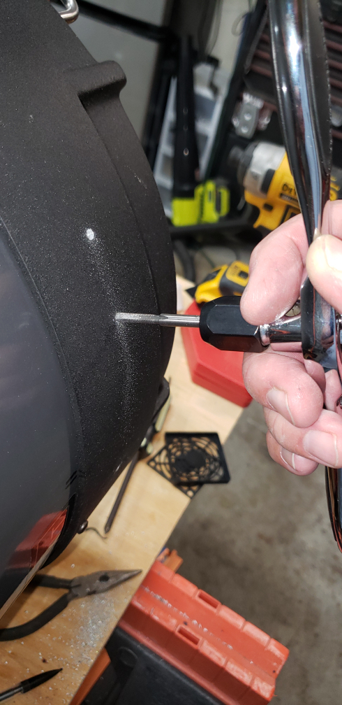 | |
| h. Vacuum OTA and surrounding areas RETURN TO TASK LIST | ||
VII. ENSURE BAFFLE COLLAR IS SNUG TO PRIMARY MIRROR | ||
| Items/Tools Needed | ||
| a. If necessary, make spanner wrench using PVC pipe or wooden square | ||
| (Note: See reference p. “Mechanical Rehabilitation of a C14 Optical Tube Assembly”, pg 21, for wood version | ||
| or create spanner using PVC pipe. I lost the link.) | ||
Procedures | ||
| a. Hand snug as tight as possible the baffle tube on the primary | ||
| b. If necessary make and use a spanner tool to tighten It was not necessary for me to make a spanner. The collar was snug. RETURN TO TASK LIST | ||
VIII. FLOCK INTERIOR OF OTA | ||
| Items/Tools Needed | ||
| a. Edmunds non-adhesive flocking paper | ||
| b. 3M Hi-Strength 94 ET Spray Adhesive Low VOC <20% | ||
| c. Lint rollers | ||
| d. PVC pipe 2” diameter to smooth flock paper (optional) | ||
| e. Vacuum | ||
Procedures | ||
| a. Measure inside of OTA from back lip to front ring mount | ||
| b. Cut flocking paper to length | 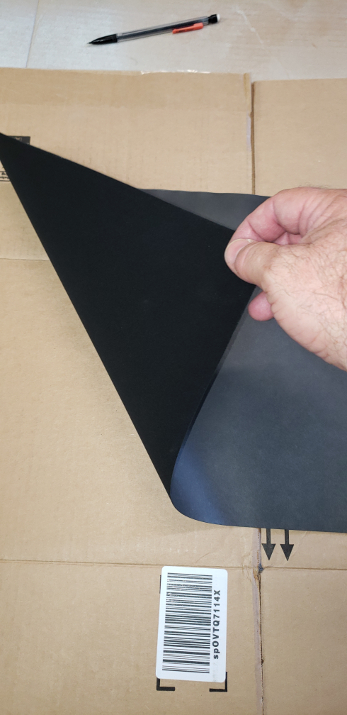 | |
| c. Cut flocking paper into (4) 12" strips to more easily place Note: Internal circumference is approximately 48". | 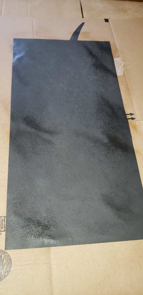 | |
| d. Spray the back of one 12" wide strip with spray adhesive | 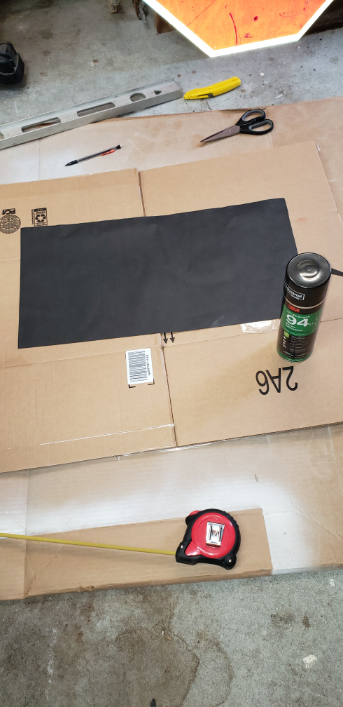 | |
| e. Lay first strip into OTA making sure it is square with OTA length covering new front vents holes | ||
| f. Line up next strip | 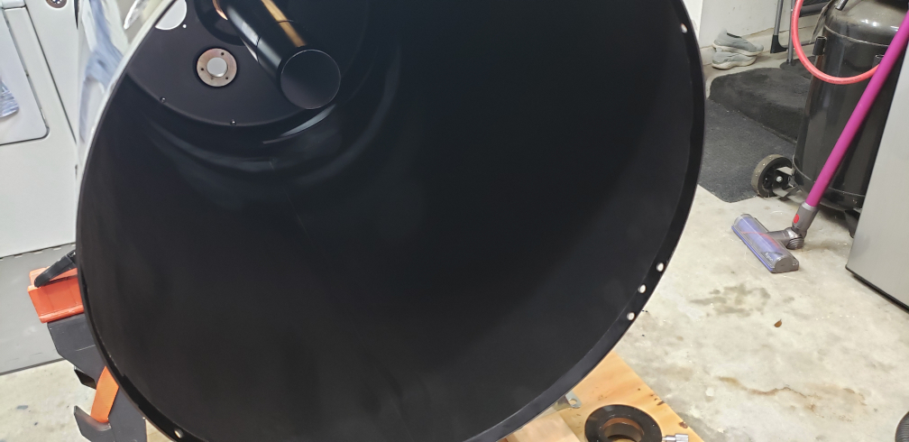 | |
| g. Cut vent holes in flocking paper | 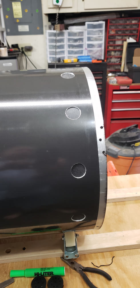 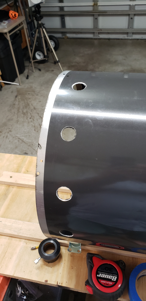 | |
| h. Repeat this 3 more times ensuring slight (1/32"-1/16") overlap for expansion and contraction of tube | 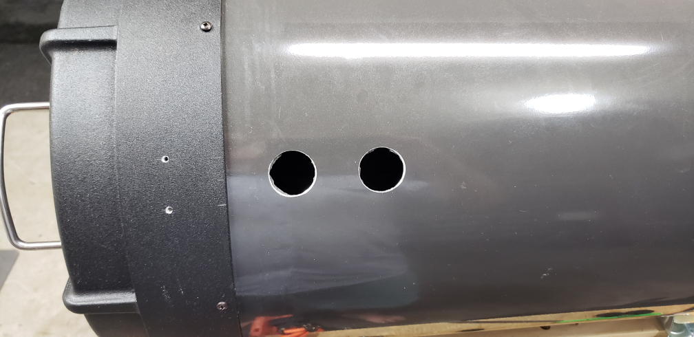 | |
| i. Use lint roller over the flocking paper many times replacing the lint tape This does two things, first it pushes on the flocking paper to get better adhesion to the OTA. Second, it pulls up loose and excess lint, fuzz, and other debris. | ||
| j. Flock interior and exterior of secondary baffle (optional) | ||
| Note: I have not done this yet. | ||
| k. Vacuum interior of OTA and surrounding areas RETURN TO TASK LIST | ||
IX. INSTALL SOFTWARE BISQUE C-14 LOCKING COLLAR | ||
| Items/Tools Needed | ||
| a. 5/32” drill bit | ||
| b. Long T-Hex wrenches | ||
| c. 1.25” hole saw drill bit | ||
| d. Drill | ||
| e. Software Bisque Locking Collar | ||
Procedures | ||
| a. Follow Reference x. Software Bisque instructions, | 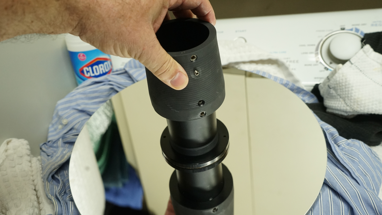 | |
| b. Drill set screw hole per instructions | 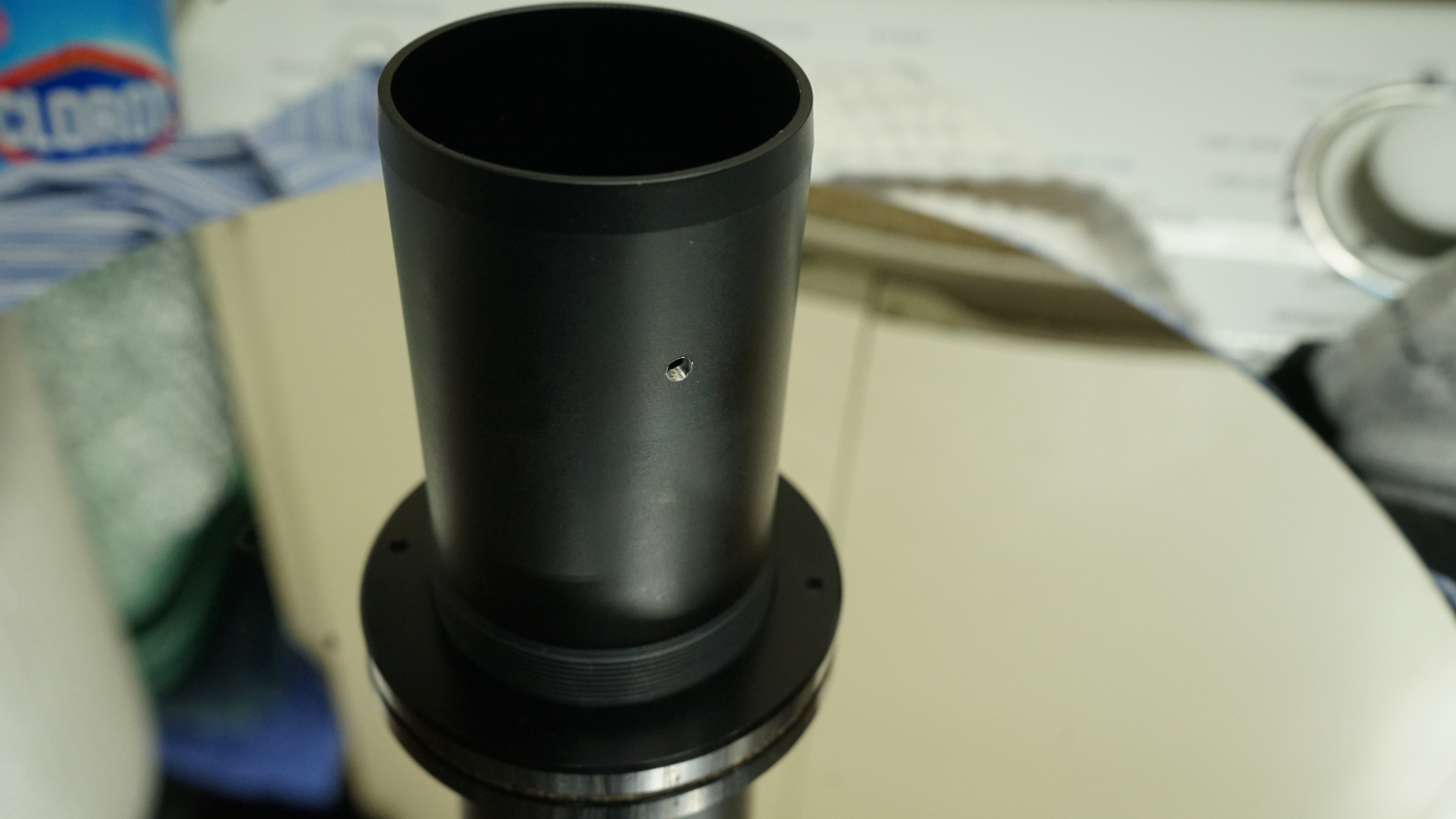 | |
| c. Cut holes in flocking paper where access holes are located | 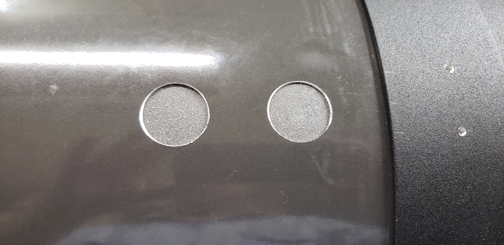 | |
| d. Clean out metal filings from drilling underneath flocking paper |  | |
| e.Ensure adhesion, reglue as necessary | ||
| f. Verify access to set screws using T-hex wrench | ||
| g. Place plugs into holes I opted to use the Heyco vent plugs here as well. My thought is that air will flow across the mirror surface further reducing turbulence. This works out well. In first uses, no discernable heat currents show in defocused star. | ||
| h. Test that plugs can be removed RETURN TO TASK LIST | ||
X. ATTACH 3 THERMOMETERS TO BACK OF PRIMARY MIRROR | ||
| Items/Tools Needed | ||
| a. JB Weld Putty | ||
Procedures | ||
| a. Route wires through 1/4" hole drill previously so as to not interfere with fans |  | |
| b. JB Weld Putty 3 temperature probes to back of primary mirror behind fan locations | 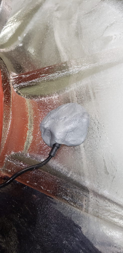 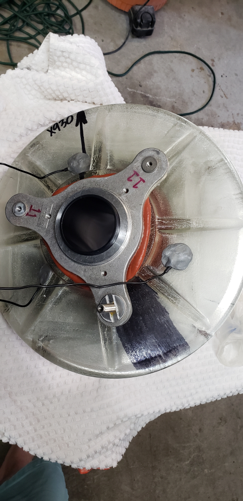 | |
| c. Let JB Weld cure 1 hour | ||
| d. Have help pulling thermometer wires back while putting primary mirror back | ||
| e. Wrap excess cable so they can fit into fan boxes | ||
| f. Install the three thermometers into fan boxes | 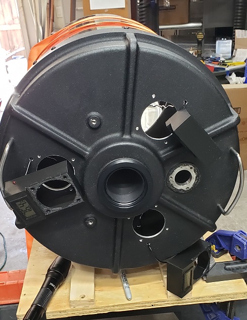 | |
| g. Bolt the (3) fan boxes with filter cover with 4 bolts to the OTA | 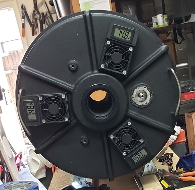 | |
| h. Tape roller the OTA inside | ||
| i. Measure and cut the new fan fabric | ||
| j. Install fan fabric into fan cover (see note below) After getting the C-14 all setup and in the observatory, I turned on the fans and noticed that the fans sounded as if they were struggling. I took this fan material out and only kept the filter that came with the fan covers. |  | |
| k. Snap the fan covers with customized Celestron logos on them onto fans RETURN TO TASK LIST | 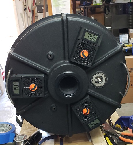 | |
XI. GREASE BAFFLE TUBE | ||
| Items/Tools Needed | ||
| a. Dow Corning 8 oz High Vacuum Grease While this was recommended by many online it may not be the best choice. | ||
| b. Paper towels | ||
Procedures | ||
| a. Use Dow grease and spread relatively thin layer evenly over the baffle tube In hind sight I put too much on the baffle tube. Once I got the scope installed I found I had a large plop of the grease on the inside of the corrector. It appeared that the "grease" became less viscous at a temperature of around 80 F. This was completely unexpected since it is rated at a high temperature. After wiping excess and cleaning the corrector the "grease" performs well. It reduced my mirror shift when focusing dramatically and I already had a small amount of shift. | 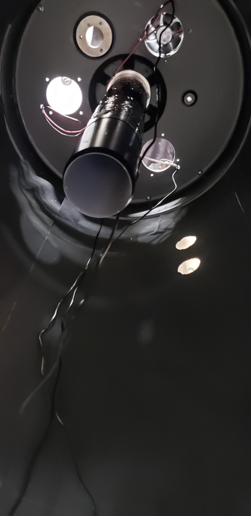 | |
| b. Slide primary mirror over baffle | ||
| c. Move up and down on baffle tube to spread grease evenly | 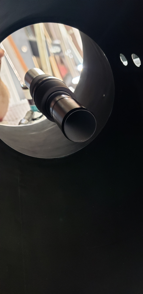 | |
| d. Wipe any excess grease | ||
| e. Install baffle retaining ring |  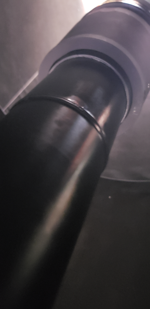 | |
| f. Reattach focuser arm into primary mirror cell | 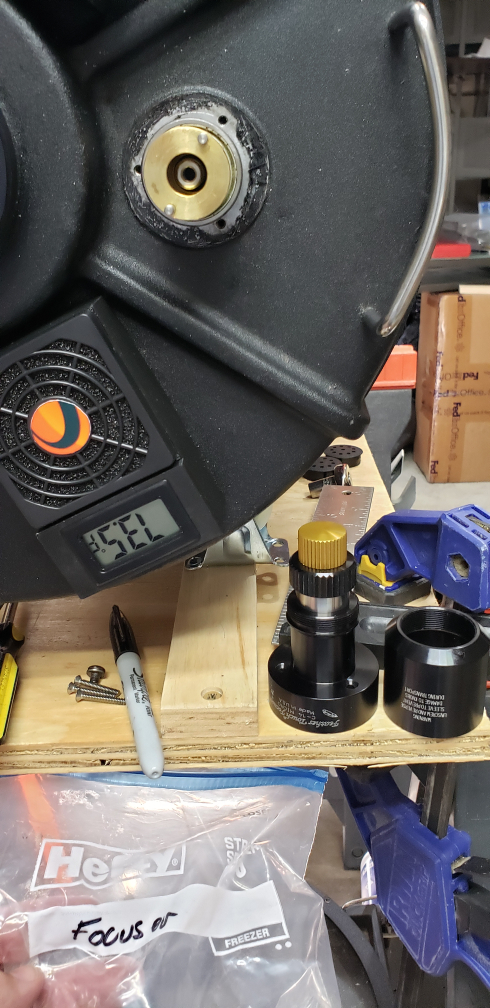 | |
| g. Reattach Feather Touch focuser RETURN TO TASK LIST | 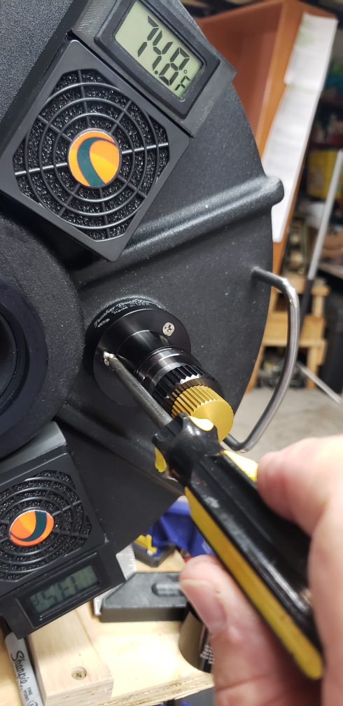 | |
XII. RE-ASSEMBLE THE C14 OTA | ||
| Items/Tools Needed | ||
| a. Phillips screwdriver | ||
| b. 11/32” nut driver for interior nuts | ||
| c. Rubber mallet | ||
| d. Block of wood | ||
| e. Tape measure | ||
Procedures | ||
| a. Install the OTA tube back onto the OTA rear cell (if it was removed during Disassembly) | ||
| b. Ensure OTA tube is properly aligned to OTA rear cell. (difficult) | ||
| c. Screw the phillips screws to attach the OTA tube onto the OTA rear cell | ||
| d. Install the upper OTA ring | 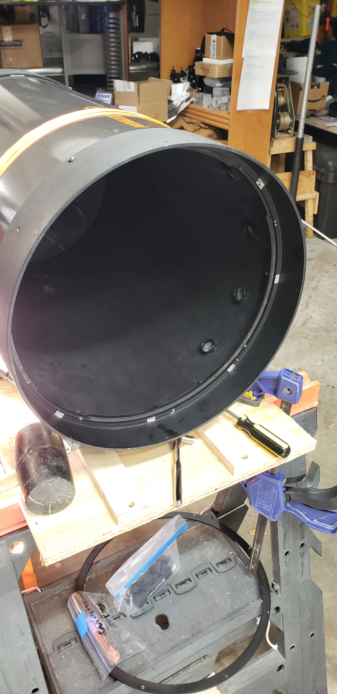 | |
| e. Align the upper OTA ring to the marks previously made (may be difficult) | ||
| f. Screw using phillips crews and wrench for nuts to attach OTA tube to the upper OTA ring | ||
| g. Do not yet install the corrector RETURN TO TASK LIST | ||
XIII. INSTALL HYPERSTAR CONVERSION KIT | ||
| Items/Tools Needed | ||
| a. Four pieces of Starizona Hyperstar Conversion Kit | ||
| b. Starizona Hyperstar Conversion Instructions and Addendum | ||
| c. Starizona Hyperstar Conversion Video | ||
| d. Silver Sharpie | ||
Procedures | ||
| a. Follow Starizona instructions explicitly: | ||
| i. Starizona Hyperstar Conversion Instructions | ||
| ii. Starizona Hyperstar Conversion Kit Addendum | ||
| iii. Video: Installing the Hyperstar Conversion Kit | ||
| b. Install corrector in properly aligned location as previously marked RETURN TO TASK LIST | ||
XIV. INSTALL FARPOINT DOVETAIL TO REPLACE CELESTRON ORANGE DOVETAIL | ||
| Items/Tools Needed | ||
| a. Farpoint Dovetail, riser blocks, and hex bolts | ||
| b. Hex wrenches | ||
Procedures | ||
| a. Attach and tighten dovetail plate to end riser blocks using provided hex bolts | ||
| b. Attach dovetail with riser blocks assembly to OTA using provided bolts RETURN TO TASK LIST | 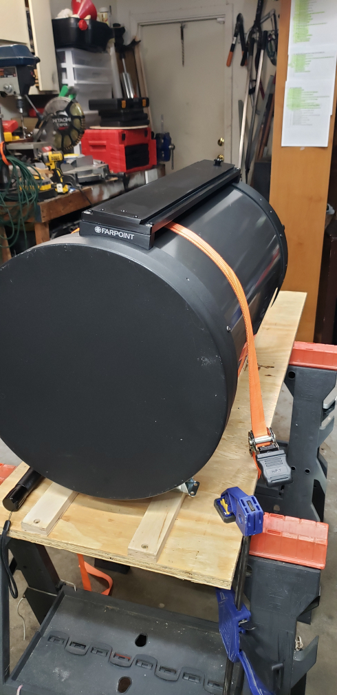 | |
XV. ALIGN AND COLLIMATE OPTICS | ||
| Items/Tools Needed | ||
| a. Hotech Advanced CT Laser Collimator Set | ||
| b. Tripod | ||
| c. White cardboard 2ft x 2ft | ||
| d. Foil 6in x 6in | ||
| e. Pin for center hole | ||
| f. Hex wrenches | ||
| g. Baader Clicklock | ||
| h. Shim material such as sticky backed flock paper | ||
| i. Howie Glatter 2” Laser | ||
Procedures | ||
| a. Check collimation and alignment per Hotech instructions | ||
| b. Hotech Advanced CT Laser Collimator Manual V8.pdf | ||
| c. Video for Hotech ACT Laser Collimator | ||
| d. Note all measurements | ||
| e. Compare measurements to those initially obtain in Step II. | ||
| f. (Optionally/additionally, follow process & procedure outlined by Mark Crossley at Wilmslow) RETURN TO TASK LIST | ||
XVI. REGREASE PARAMOUNT ME | ||
| Items/Tools Needed | ||
| a. Toothbrush | ||
| b. Paper Towels | ||
| c. Artist paint brush 3/8"-1/2" wide | ||
| d. 3/32" hex wrench | ||
| e. Lubriplate Motor Assembly Grease Series 105 | ||
Procedures | ||
| a. Remove RA worm block cover using 3/32” hex wrench | ||
| b. Follow instruction in Software Bisque video. | ||
| c. Repeat for DEC worm gear RETURN TO TASK LIST | ||
